


The first figure of a rim indication (e.g 6.00Ix10) indicates the rim width in inches and the last figure indicates the diameter of the rim in inches. The letter after the first figures indicates the type of flange. The symbol between the letter and the last figures indicates the type of rim, either a well base rim (x), one part welded, or a flat base rim (-), two parts, bolted together.
In these rims, an integral tube is welded in the centre of the rim. In this tube, there are bearings fitted, which guarantee a smooth rotation and correct load. There is a wide range of bearing specifications with different bore diameters and load characteristics dependent on the application. These rims are used for several applications including materials handling equipment, wheelbarrows, agricultural and horticultural equipment, static caravans and trailers.
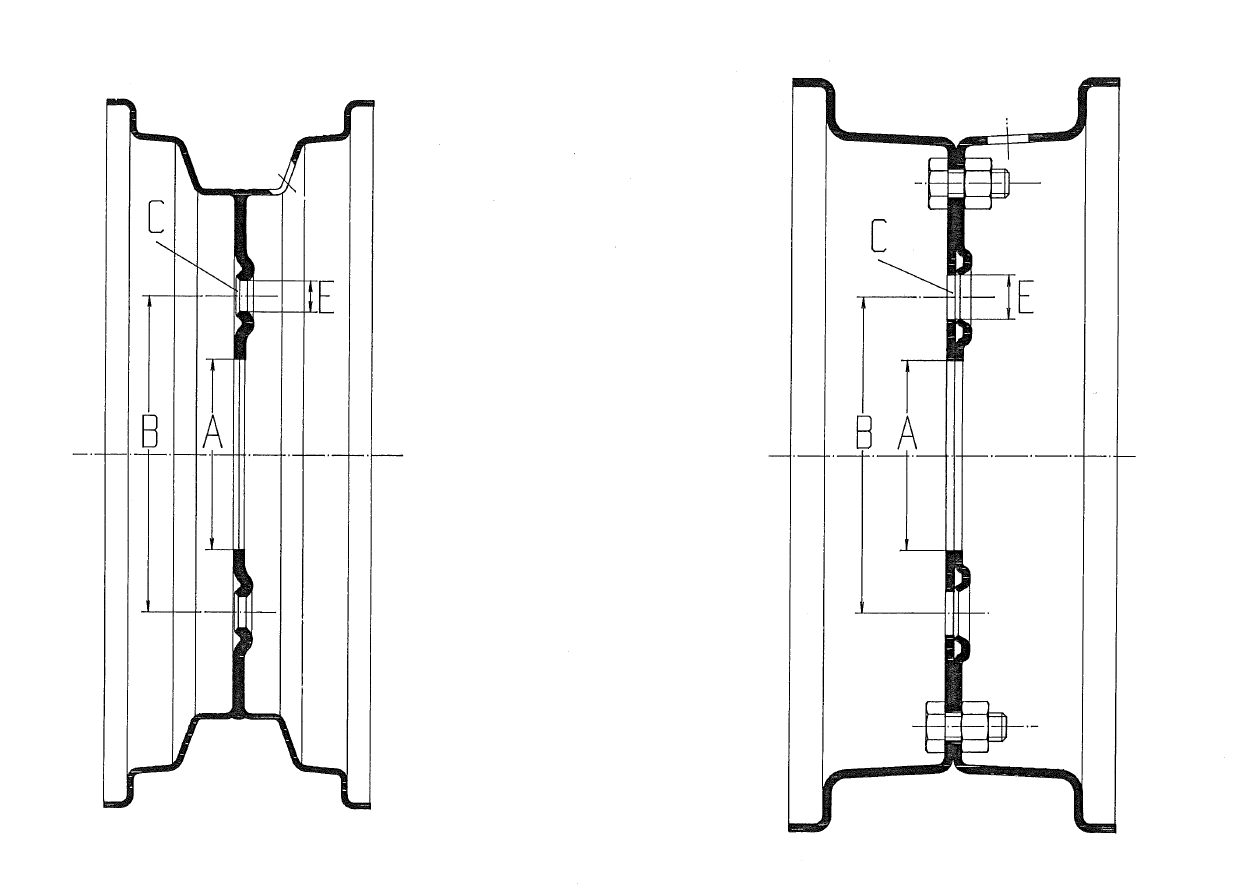
Left image: the one-piece welded rim, right image: two-piece divided rim
These rims have stud holes which correspond with the Pitch Circle Diameter (P.C.D.) of the studs on the hub. These rims are used for different purposes, including slow speed industrial application, agricultural use and on high-speed trailers and caravans.
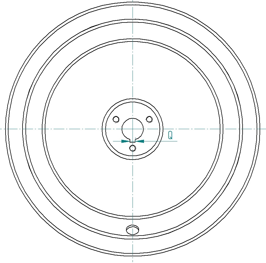
The hub connections such as centre hole, Pitch Circle Dia-meter and the number and size of stud holes are detailed on the drawing below:
| Symbol | Name | Unit | Description |
| A | Type | Rim is welded to 1 single component or consists of 2 components that are bolted together. | |
| B | Width of rim | inch | Width between the flanges in mm. |
| C | Diameter of rim | inch | The diameter of the bead seat in mm. |
| D | Flange type | Type of the flange: the shape of the rim profile. See ETRTO for more information. | |
| E | Offset | mm | The offset of the mounting plane with respect to the midplane of the rim in mm. |
| F | Hump | 0 / 1H / 2H | Number of safety humps to prevent the tyre from coming off the rim. |
 |
|||
| G | Rim thickness | mm | Material thickness of the rim in mm. |
| H | Hub length | mm | Length of the hub in mm. |
| J | Fitting length | mm | Distance between the mounting surfaces of a rim with a hub in mm. |
| K | Fitting type |
Left image below: left: the rim is designed to be mounted in a fork, usually two identical axle holes. |
|
 |
|||
| L | Hub diameter | mm | The outer diameter of the hub in mm. |
| M | Bearing type | Type of the bearing in the hub: ball bearings, Taper roller - Spherical roller – Roller bearing- Bush type - Plain Bronze - Self lub. – Nylon - None (plain bore) | |
| N | Bearing number | Number of the bearing to identify the bearing dimensions. | |
| O | Bearing quality | Premium or standard quality bearings? | |
| P | Max axle hole | mm | The diameter of largest axle hole in mm. |
| P | Min axle hole | mm | The diameter of smallest axle hole in mm. Could be identical to the largest hole. |
| Q | Keyway width | mm | In case of keyway: the width of the slot in mm. |
 |
|||
| R | Grease nipple | yes/no | Grease nipple in hub required? |
| S | Type of cap | End cap required. If yes: specify plastic or metal cap. | |
| T | Sealings | Additional sealings required to protect the bearings. If yes, please specify a type. | |
| U | Hub hole diameter | mm | Minimum hub hole diameter in mm. |
| V | pitch circle diameter | mm | The diameter of the pitch circle of the mounting bolts to the axle in mm. |
| W | Number of bolt holes | The number of mounting bolts to the axle in mm. | |
| X | Diameter bolt holes | mm | The diameter of mounting bolt holes to the axle in mm. |
| Y | Shape stud holes | The shape of the edge of the mounting bolt holes. e.g.: R14 or 60o, cylindrical, spherical or conical. | |
| Z | Valve hole diameter | mm | Diameter of the valve hole in mm. |
| AA | Markings | yes/no | Markings of rim size and drawing number required on the rim? |
| AB | Valve guard | yes/no | Steel cap to protect the valve required? |
| AC | Drainage holes | yes/no | Holes that prevent water collection in the rim required? |
| AD | Inner disk thickness | mm | Material thickness of the centre plate in mm. |
The execution of the stud holes is very important for the fitting of the rim to the hub. Vlukon rims are pressed with standard stud holes with a stud seat of 60 degrees conical or spherical, depending on the type of rim. Other specifications of stud holes can be manufactured on request.
Type A and B Stud holes


CE & CD (image below) have conical countersink stud holes


| CONICAL COUNTERSINK SIZES | |||
| No. | diameter | Internal thread | |
| 1 | 12,5 | 60º | M10x1,25 |
| 2 | 13,5 | 60º | M12x1,50 |
| 3 | 14 | 60º | M12x1,50 |
| 4 | 15 | 60º | M12x1,50 |
| 5 | 16 | 60º | M12x1,50 |
| 6 | 18,5 | 60º | M14x1,50 |
| 11 | 10,5 | 90º | M10x1,25 |
| 12 | 12,5 | 90º | M12x1,50 |
DE & DD (image below) have Spherical countersink stud holes

| SPHERICAL COUNTERSINK SIZES | |||
| No. | diameter | Internal thread | |
| 1 | 12 | R10 | M10x1,25 |
| 2 | 15 | R12 | M12x1,50 |
| 3 | 16 | R12 | M12x1,50 |
| 4 | 18,5 | R12 | M14x1,50 |
| 5 | 18,5 | R14 | M14x1,50 |
The offset is the distance from the centre of the rim to the mounting face of the nave plate. The offset can be positive (+) or negative (-). The drawing below details the offsets available:

PAINT FINISH OF VLUKON RIMS.
Vlukon B.V. has, for many years, used a very modern method of finish painting using a powder coating process.
Powder coating is:
• Degreasing
• Phosphating
• Washing
• Drying
• Powdering
• Harden in oven
This guarantees the protection of high quality.
You will find the range of our RAL colours on Rim Colours. Deviant colours can be powdered on request at a surcharge. This surcharge depends on the quantities to be delivered.
LOAD CAPACITY.
The load capacity, as indicated, is the maximum load capacity under operational conditions as stated, fitted with pneumatic tyres. Since 2018 we only indicate load capacities for specific purposes, to make sure we select the perfect wheel for your application, with enough load capacities and safety factors but not overly dimensioned.